Siamo nel 2020 e sembra esserci un rinnovato interesse nei confronti delle BBS. Per chi sapesse cosa siano, in breve e in modo molto approssimativo BBS (Bulletin Board System) erano dei servizi telematici (in voga negli anni 80 - primi 90) di messaggistica e scambio file, che "viaggiavano" sulla comune linea telefonica, e i cui nodi erano gestiti in gran parte dalla comunità di hobbisti e amatori. Ci si collegava tramite modem spesso alla velocità di 1200bps (150 byte al secondo) e l'interfaccia utente era esclusivamente testuale, con caratteri ASCII che simulavano "grafica". Oggi le linee telefoniche analogiche non esistono praticamente più e le BBS sopravvissute si sono spostate su Internet, dove ne nascono anche di nuove. Per potersi collegare tramite un vecchio computer serve ovviamente un collegamento seriale, ed è semplice trovare online progetti e realizzazioni di modem Wi-Fi, cioè dispositivi che connettendosi alla porta seriale RS-232 emulano il funzionamento di un modem analogico, collegandosi però in TELNET a

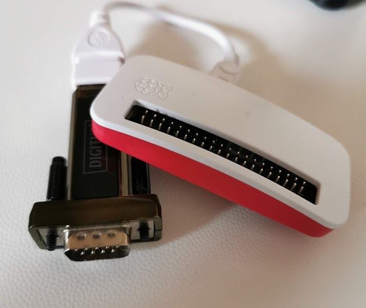
un host remoto (specificando la porta). Avendo però a disposizione un Raspberry PiZeroW e un adattatore USB -> RS232 è possibile realizzarsi in casa un modem Wi-Fi a "costo zero" (oltre quello del Pi e dell'adattatore!) senza bisogno di saldature e modifiche. Ecco quindi un breve tutorial su come realizzarlo. Innanzitutto occorre un adattatore USB -> Seriale RS232. Ho utilizzato nel caso specifico un modello Digitus, disponibile anche su Amazon (qui il link al prodotto), che ha funzionato al primo colpo sul PiZeroW senza bisogno di ulteriori "smanettamenti". Installazione del sistema operativo Il PiZeroW è fornito di solito con una microSD con già installato Raspberry Pi OS. Supponiamo però di partire da zero, avendo a disposizione una microSD vuota. Il modo più semplice e immediato per installare un sistema operativo sulla microSD è utilizzare il tool RPI Imager, distribuito gratuitamente a questo link. Al primo passaggio, CHOOSE OS, scegliete "Raspberry Pi OS (Other)", e di seguito la versione leggera "Raspberry Pi OS…

PURPOSE Allow the Apple-1 computer (and Replicas) to handle connections with telnet protocol (either outgoing or incoming) in order to connect to existing BBSes or chat sessions (keyboard-to-keyboard) IMPLEMENTATION An Asynchronous Communications Interface Adapter (ACIA) 6551 has been used. It was commonly used as an UART (Universal Asynchronous Receiver-Transmitter) for the 6502 microprocessor; it is addressed through a 74154 (4 to 16 lines decoder/demultiplexer). UART is then connected to an ESP8266 that acts as an Hayes-compatible Wi-Fi Modem. The ESP8266 must be programmed following the instructions: https://1200baud.wordpress.com/2017/03/04/build-your-own-9600-baud-c64-wifi-modem-for-20/ A small Terminal program written in Assembly is used to interact with it. CIRCUIT & ADDRESSING Power is derived from the 5V main bus. 74154 acts as Address Decoder as described below. Apple-1’s Address lines from A12 to A15 (A15 is MSB) are connected to 74154’s A...D input lines (D is MSB) in order to split the addressable 64 kiB into 4 kiB chunks. This operation is very common in this architecture. Although it would have been possible to use the signals R, S and

T (coming from the mainboard’s 74154, which perform the same operation) they were not used. R line is commonly used with Cassette Interface; S and T are usually not used (not connected) on to original boards. To guarantee the functionality of the interface with unmodified original boards the 74154 perform its own “four most significant bit” Address decoding. It has been decided that 75154’s output named “7” (corresponding to Addresses from $7000 to 7FFF) is assigned to the 6551. To perform this selection, output “7” has been connected to 6551’s /CS1 pin. Other outputs might be used in the future in order to add functionality to the board, i.e. EPROM etc. The other 6551’s Chip Select pin, CS0, is not used and it has been tied to +5V. Data Bus signals (D0 to D7, D7 is MSB) are connected to 6551, as well as /IRQ, ɸ2, R/W and /RES. 6551’s RS0 and RS1 inputs are respectively connected to Apple-1’s A0 and A1 Address lines: they will be used to read and write the four registers of the 6551. 6551’s…

by Claudio Parmigiani PURPOSE Allow the Apple-1 computer to generate sounds and simple melodies via BASIC or Assembler. IMPLEMENTATION A SID (Sound Interface Device, MOS 6581) has been used. It is addressed through a TTL logic, which will be explained later. Some circuitry has been added to ensure compatibility with the MOS 8580. An amplifier has also been added in order to provide an adequate output level. CIRCUIT POWER 5V is taken directly from the Expansion Bus 12V (for 6581) or 9V (for 8580) is derived from the “12V Unregulated” on the Expansion Bus. Raw voltage is about ~20V (not stabilized). A jumper is used to select the right voltage. FILTERS Typical 6581’s CAP1/CAP2 filter capacitors value is 470pF. These capacitors are present on the board. It is possible to select other capacitors by switching another couple of jumpers. Alternative capacitors must be connected to the appropriate sockets. AUDIO AMPLIFIER A simple 1-transistor (2N2222) audio amplifier is used. Output is

connected to a stereo 3.5mm jack female connector. MISCELLANEOUS POTX/POTY SID’s pin are connected to auxiliary connector, for future use. ADDRESSING Connections to /RES, R/W and ɸ2 signals are by the book, just like Data Bus (D0 to D7) and Address Bus (A0 to A4) signals. Chip Select (/CS) signal is derived from a TTL 74LS10 logic port, which provide a logic LOW signal when: Address bus is $C8xx ɸ2 is at logic HIGH level. $C8xx address is resolved as follows: HEX: C 8 0 0 ADDR LINE: A15 A14 A13 A12 A11 A10 A9 A8 A7 A6 A5 A4 A3 A2 A1 A0 BIN: 1 1 0 0 1 0 0 0 0 0 0 0 0 0 0 0 ↓ ↓ ↓ ↓ ACTION: pick "R" LOW signal pick A11 HIGH signal does not care does not care “R” signal is usually hard-wired on the CHIP SELECT section of the Mainboard of the Apple-1. It is usually connected…